
Frank Badalson sets the bar in Hemi engine restoration. Here’s how he does it.
By Cliff Gromer and Frank Badalson Photos by Cliff Gromer
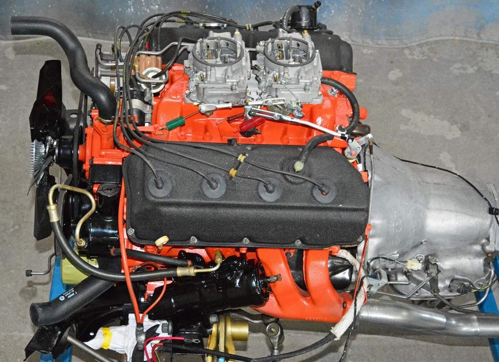
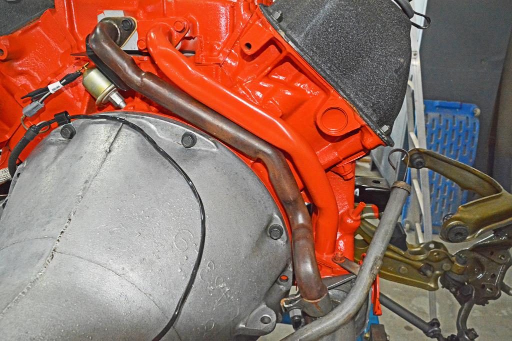
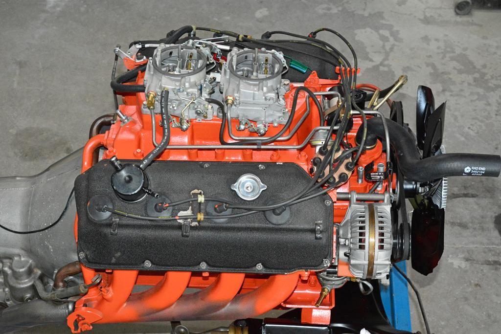
This overall view of the left side of the ’71 Hemi shows power steering high pressure hose dated and correctly plated. The pump has been detailed and shows correct mounting. Original oil filter hoses are on as they would be on the assembly line. Note the positive battery cable, and a general view of the carbs and linkage. We’ll show close-ups as we move along.
A correctly detailed engine goes beyond “pretty.” A nice fresh orange paintjob and shiny metal on a ’71 Hemi may get you compliments from the average Mo’fan at car shows and if that’s what you’re looking for, you might as well skip this article. What we are showing here is what the Hemi looked like when fully assembled at the factory and ready to go into a car, complete with transmission and exhaust—from the bottom. It’s the fine details that separate a platinum quality engine restoration from the also-rans, and it’s the fine details based on research and his 45 years experience in the Mopar world that has made Frank Badalson one of the premier Mopar restorers in the hobby today. You’ll find all these photos and more, such as his world-famous paint drips, on our free website so you can knock yourself out by inviting over all your friends and blowing them up to full screen size on your 80” plasma TV.
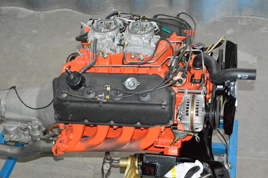
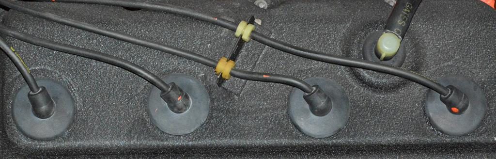
Overall view of the right side shows paint daubs on the plug wires. Also shown is the original “76” alternator with the original “059” pulley.
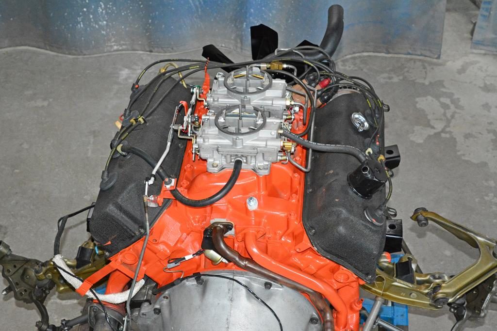
Overall rear view.
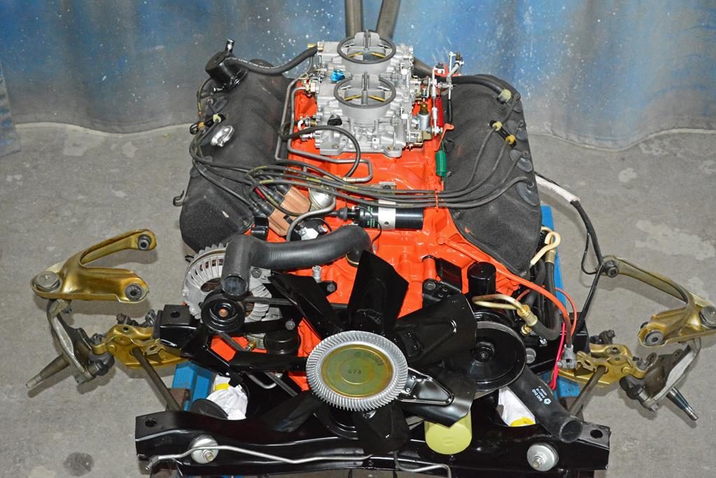
Front view. Negative battery cable is painted with the engine. Intake, dipstick tube, water pump neck and fuel pump mounting area are all taped off prior to painting.
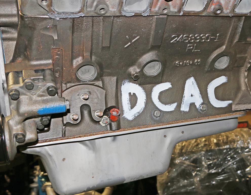
This is the block that’s been stripped. Frank reproduces the letters A,B,C and D that were applied at the Marysville plant that indicate bore size so correct size pistons and rings can be fitted. Many restorers eliminate this step as the letters will be painted over. Frank believes that’s the wrong attitude in the restoration business. He doesn’t skip any steps and has built his reputation on setting the standard for correctness. The engine is NOT primed before painting (a common error)—it’s just cleaned and then sprayed with engine enamel. You have to have all the trim that the factory had on the engine when they painted it, then assemble it afterward.
The distributor, cap and wires are apparently inserted after the engine is painted. The wires are dangling as they are put in with the distributor so they hit areas of fresh paint while they are dangling. Most likely, the distributor and wires are an assembly probably inserted as the engine is in final stages of prep. The distributor is “staked” then the engine makes it to the paint area. The distributor is pulled out, wires and all. Valve covers are sloppily taped off; holes are taped–usually sloppily. Keep in mind this is a quick process, they are not concerned with pretty. Just get it done quick.
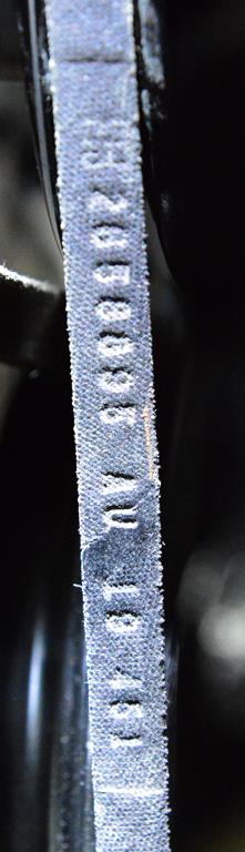
Original Hemi fan belt p/n 26508895.
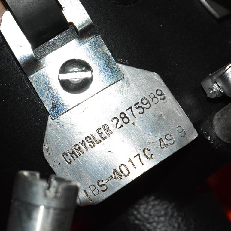
The original distributor tag. Note the date: 499 49th week of ’69. It’s common to see a part made in the 49th week of ’69 in a car that was assembled in ’71. The factory wanted to use up all remaining parts in this the last year of the Hemi. You’ll see the same thing when we get to carburetors.
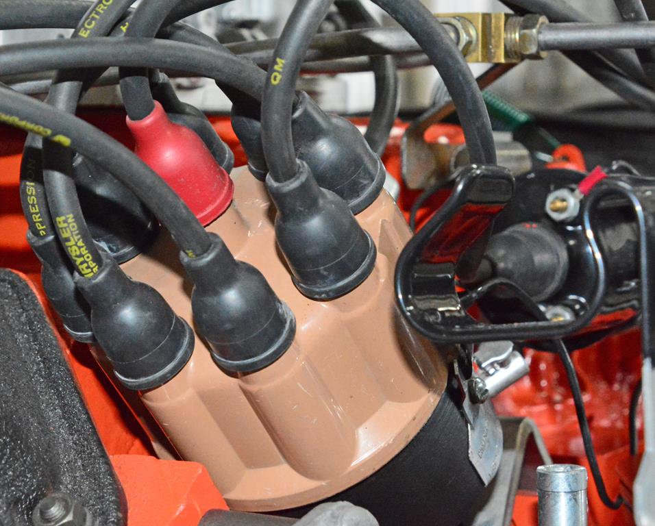
The distributor coil wire has a red boot. The coil’s boot is black.
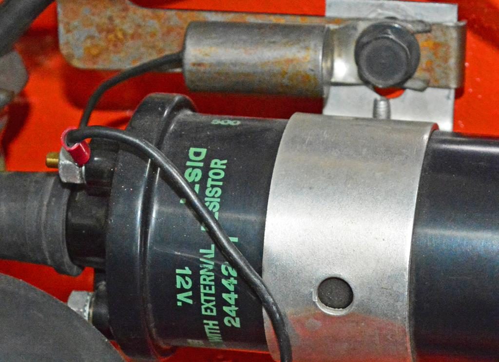
While we’re at the coil, note the original radio suppression condenser—always mounted on the battery side, never the distributor side of the coil.
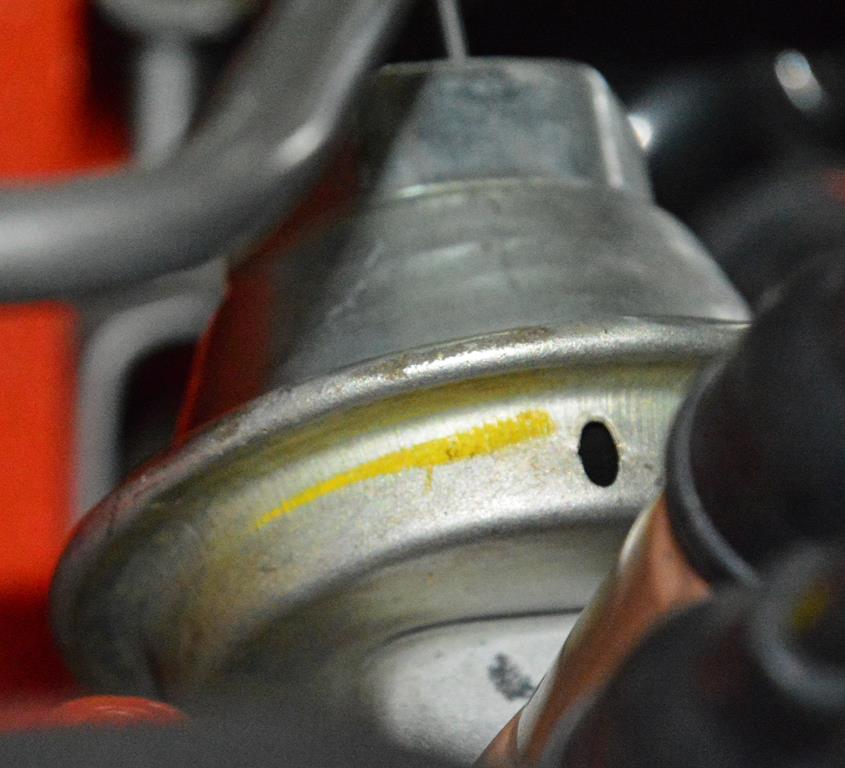
Original vacuum advance canister with an inspector’s yellow hash mark.
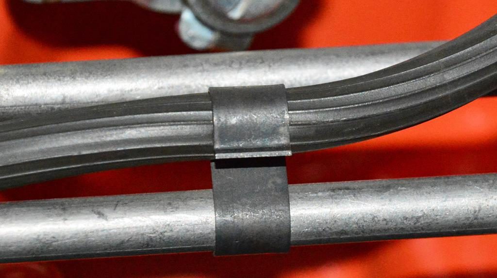
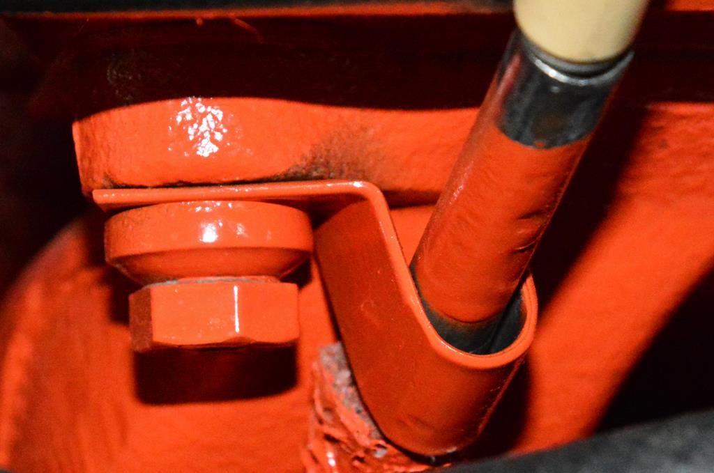
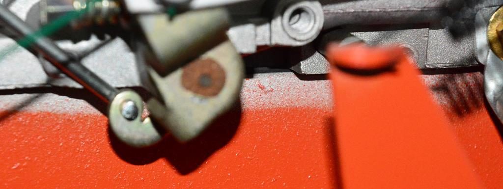
Correct mounting of the distributor vacuum advance line and the S clip. Typically this is incorrectly attached to the outer fuel line that goes to the rear carb. This is the ribbed line used on the assembly line.
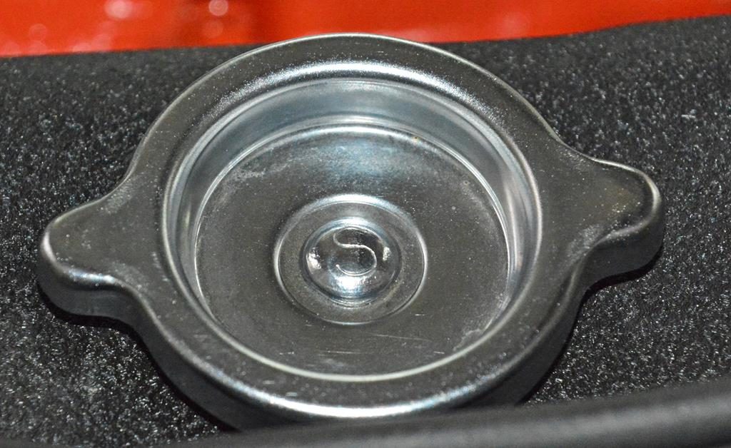
Original oil filler cap is a deep dish chrome design not stepped down. The unique cap was used on ‘70-‘71 Hemis only and shows a “S” (for the vendor—Stant) on the head of the rivet.
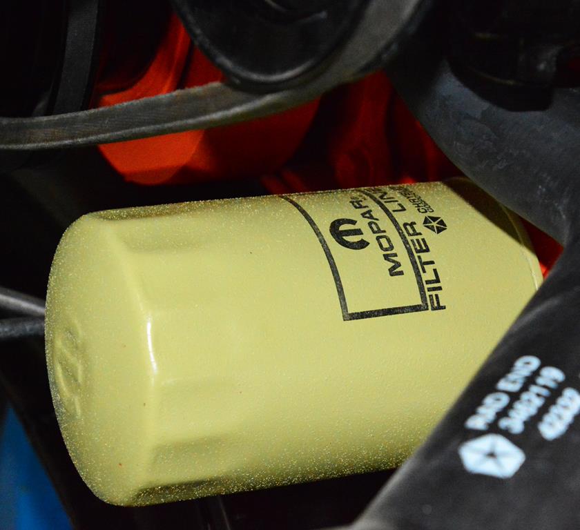
Correct assembly line oil filter.
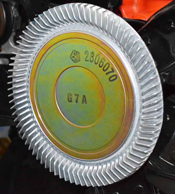
Dated fan clutch with original blades. Note that even though build sheets for Hemis in 1971 may show “112” for the 3462112 fan clutch, many ‘71 Hemis have the 2806070 fan clutch installed from the factory. The original fan clutch for this engine was an “070” with a date of G7A = July 7, 1970.
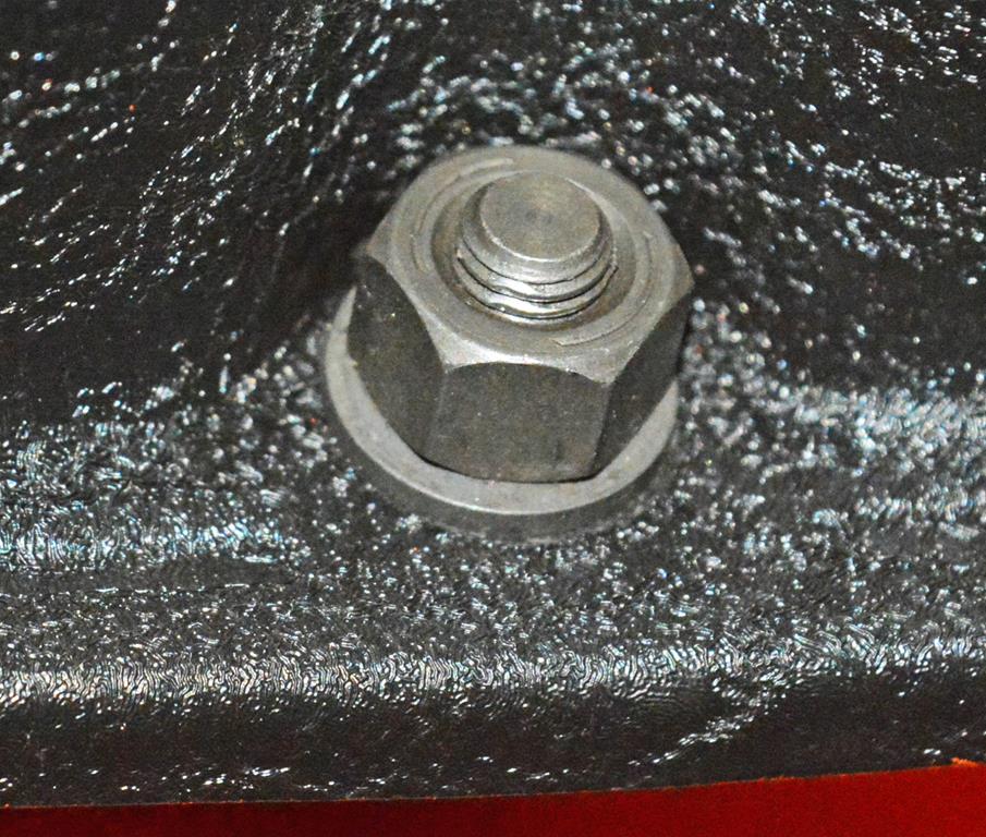
’71 nuts that hold the valve covers are unique to ’71 Hemis only. They are taller and have a smaller washer than ’70. The nuts are 1/4-28, 7/16” hex approx .35” thick and the washer OD is .54”.
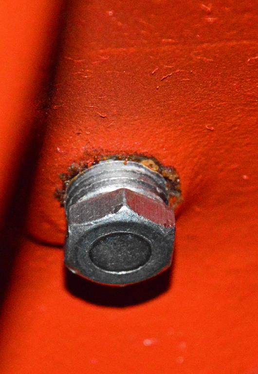
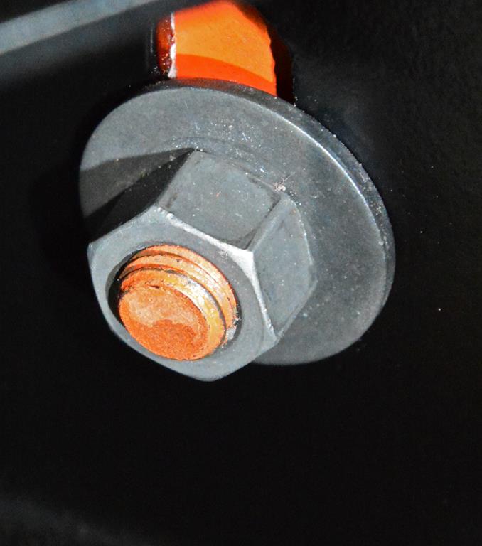
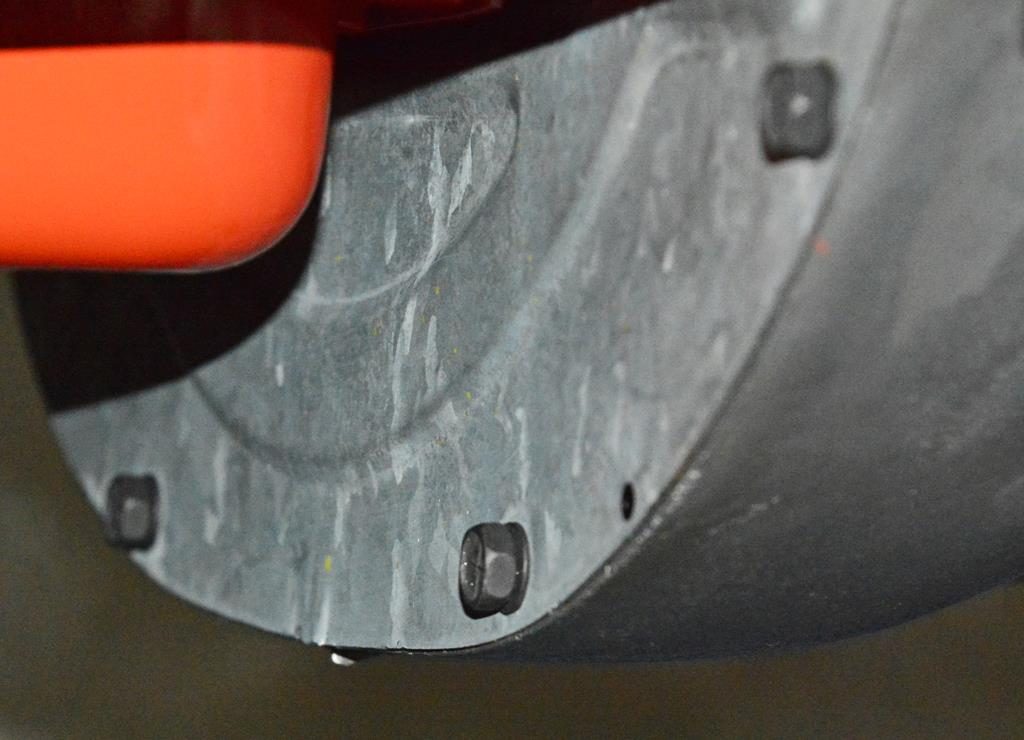
Engine drain plugs are something that almost everybody gets wrong. They are not painted with the engine and have no sealer or tape.
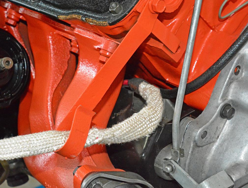
The positive battery cable has a special heat resistant covering because of the way the Hemi manifolds are designed. The bracket for left cylinder head keeps the cable away from heat. Note the way the cable routes from behind the starter heat shield up towards the top through the bracket which is missing on a lot of restos.
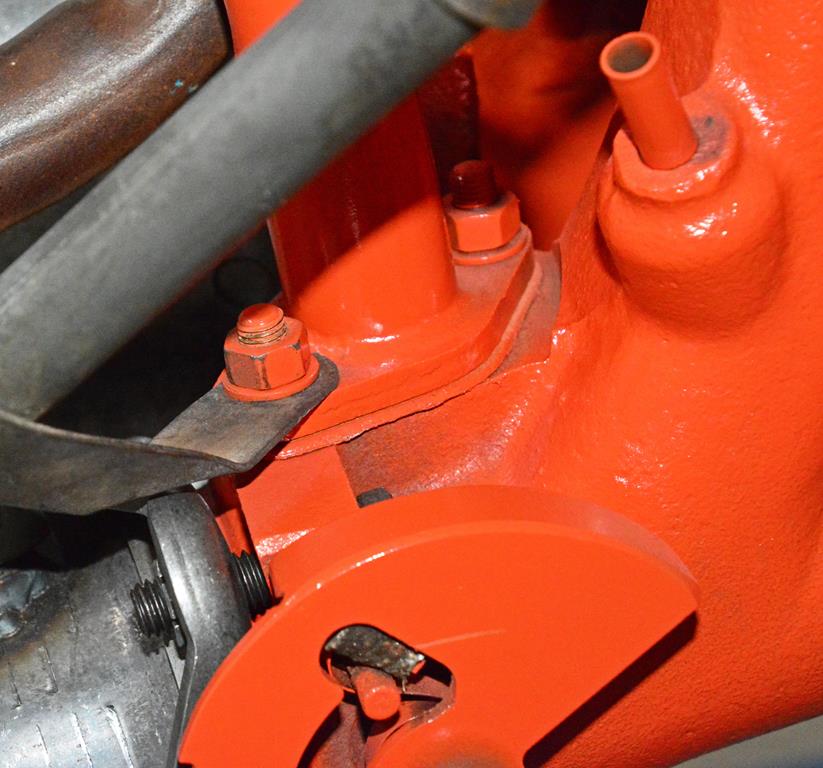
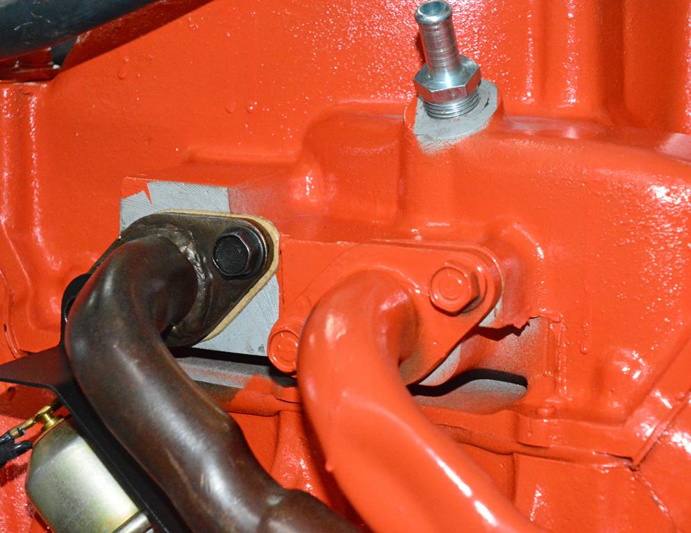
The heat riser is another common error area. The hard to find asbestos fiber anti-rattle insulator (the black piece above the pin at the bottom of the photo) is usually missing. Note that a lot of ‘71s had a ’70-style right side exhaust manifold with the protruding tube. This is for the ’70 choke tube. They still used the ’70 leftovers in ’71 even though there’s no choke tube setup because ‘71s used a manual choke.
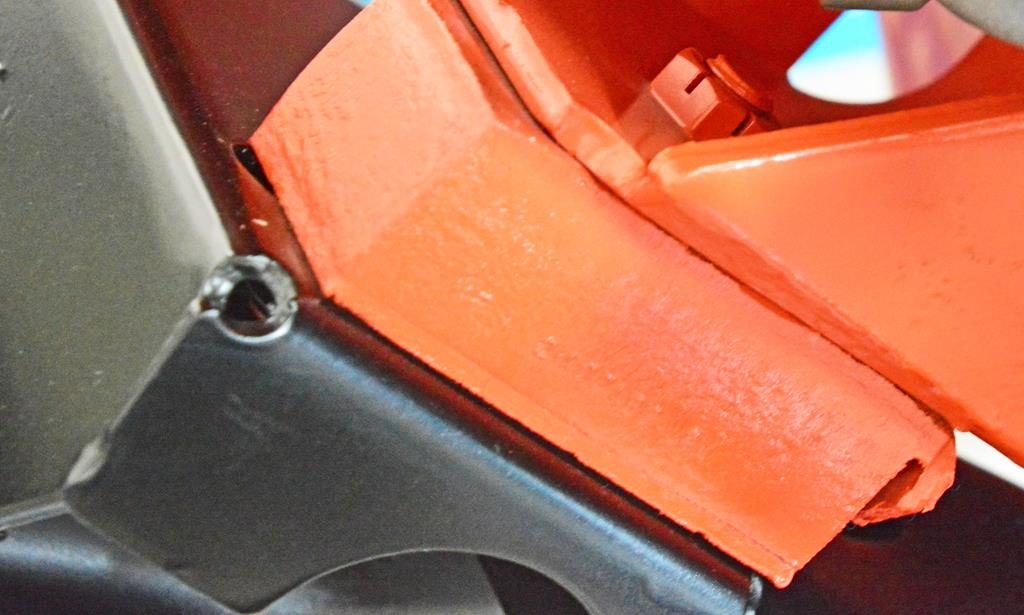
The unique front mounting tab for the Hemi starter heat shield bracket. The tab is part of engine assembly so it’s orange. The heat shield goes in afterward so the shield and the bolt are not painted.
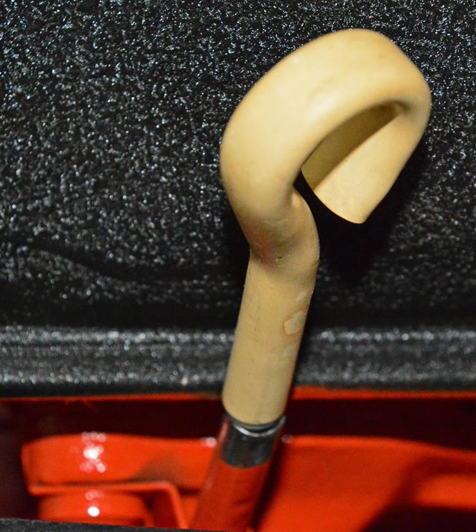
Original Hemi oil dipstick tube and handle. The insulator for the tube covering is below the retaining bracket. Top of tube is bare as it is taped off during painting. Handle has the proper rubber insulation.
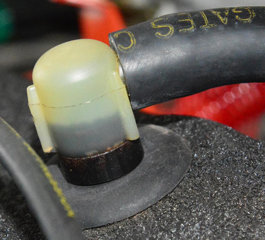
Correct NOS PCV valve does not have a silver base. This original valve has the correct dark base.
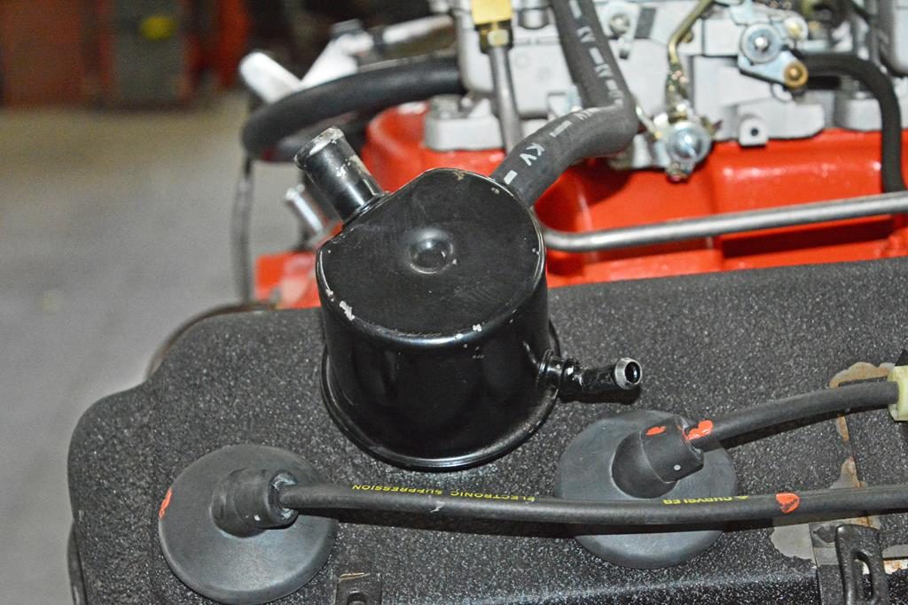
All ‘71s have a 3-nipple breather.
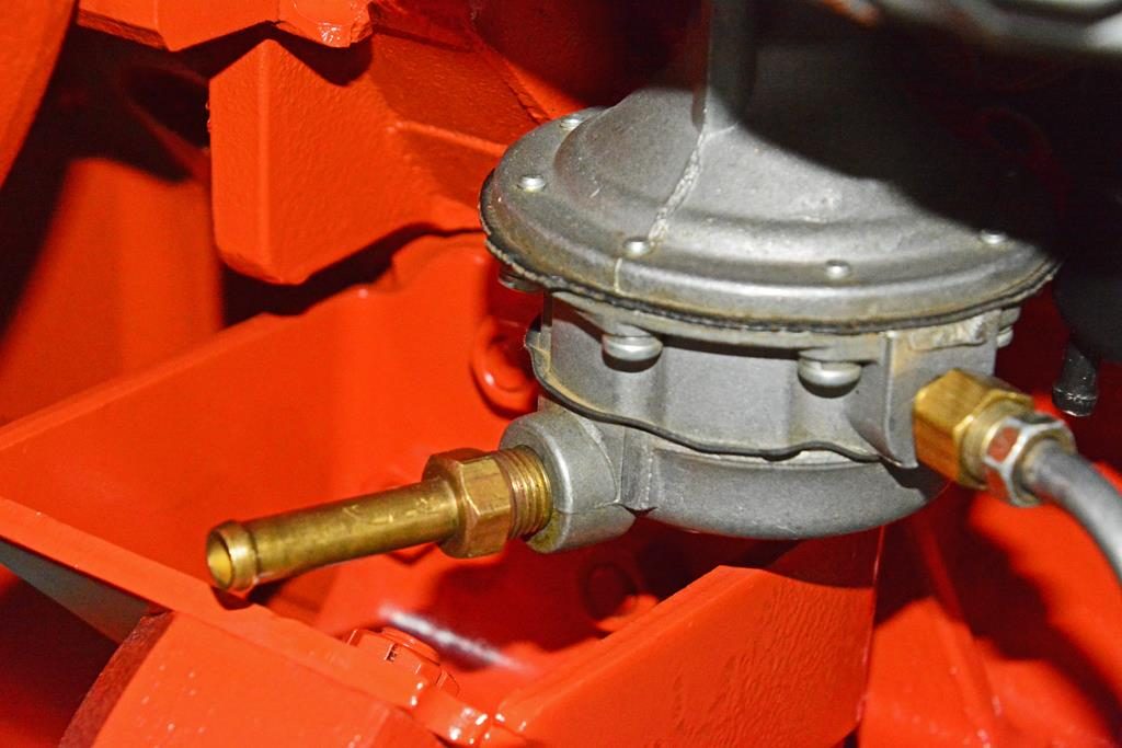
Original fuel pump inlet fitting is unique to a Hemi in style and length.
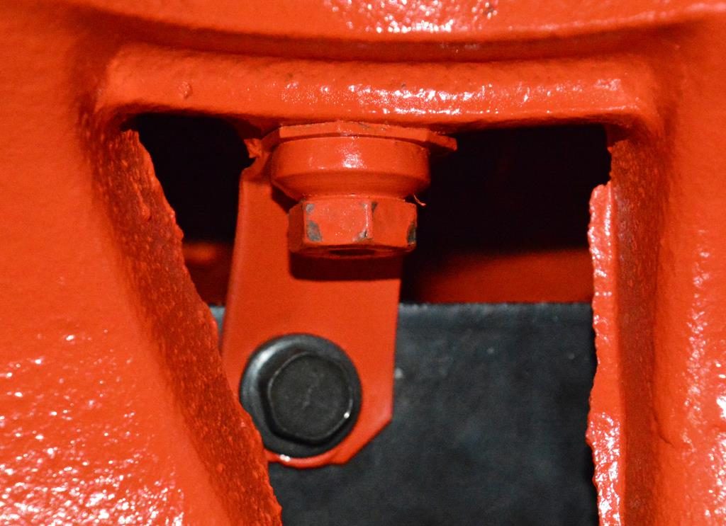
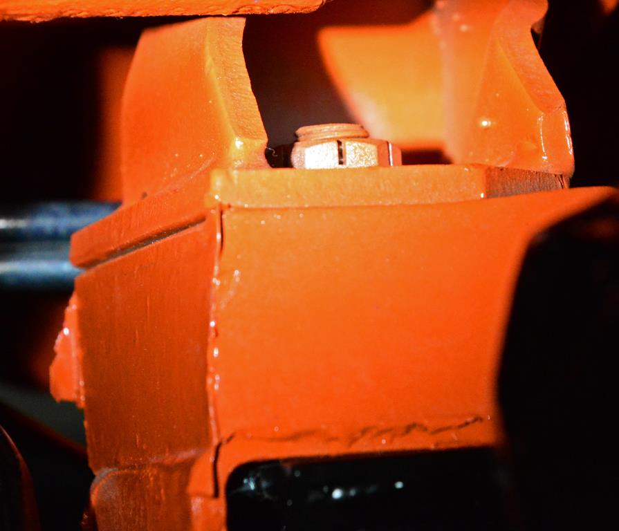
Right below the fuel pump is right side motor mount (always painted) showing the unique-to-Hemi Marsden (slotted) nuts attaching the rubber insulator to the K-frame. The underside of the K-frame shows the unique nut with spin washer, properly plated. There are two of these.
Left side motor mount.
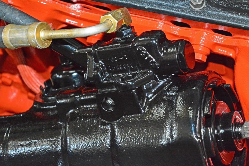
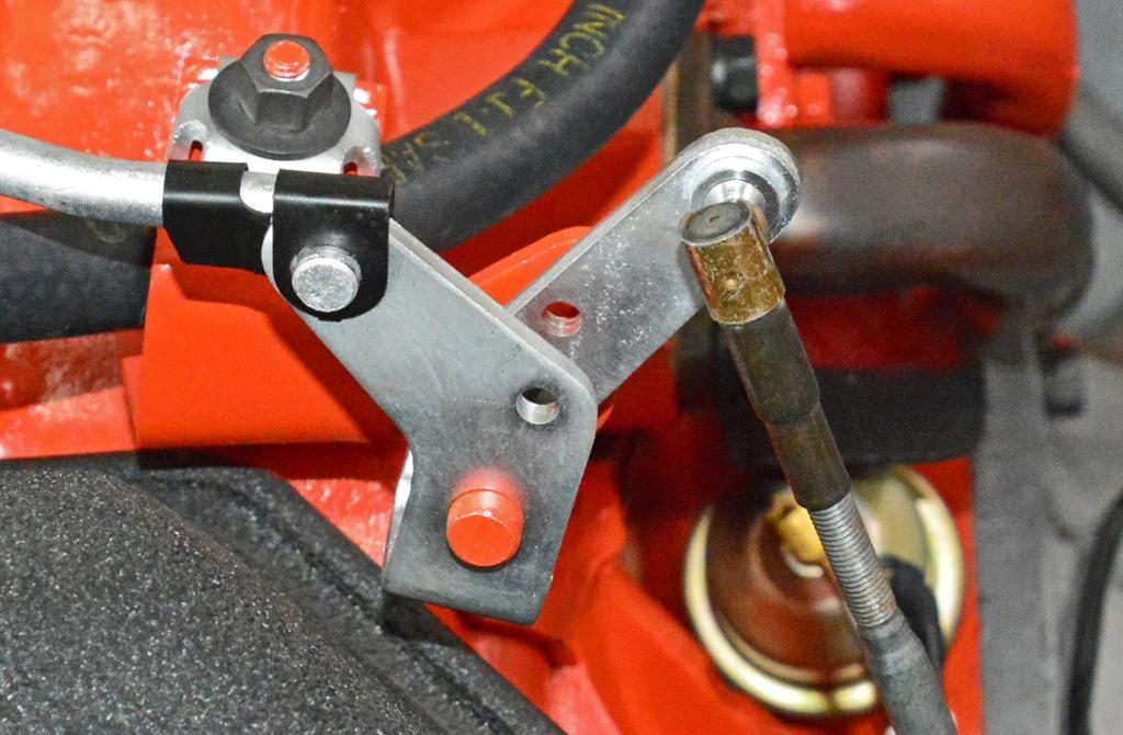
The power steering gear is always painted black. Note the correct Hemi 90 deg. angle fitting and original dated Hemi PS hose. This hose is dated 263 8 (263rd day of 1968). It’s very common to see this date on ’70-‘71 Hemis. The correct engineering number on the hose is 2537701.
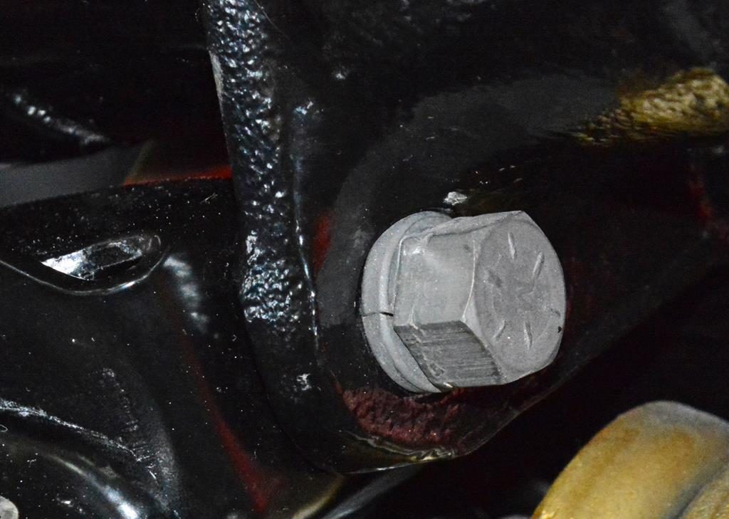
Correct original bolts that hold that hold PS gear to the K-frame. In this case, they’re hex. This is a unique design Grade 8 hex bolt with heavy duty washer.
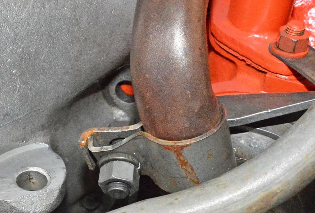
Configuration of the heat tubes at the back of the intake-one is painted on the line. The unpainted tube that goes to the H-pipe is put on afterward and has a correct clamp, nut and bolt. Nipple at top is for power brakes. Generally, these areas were taped off during paint leaving bare spots. Also note the Hemi-only auto trans dipstick tube mounts to the outer heat tube stud. Correct clip holding the Reverse wire neutral safety switch wire oil pressure sending unit and oil pressure resistance wire bracket on the bellhousing.
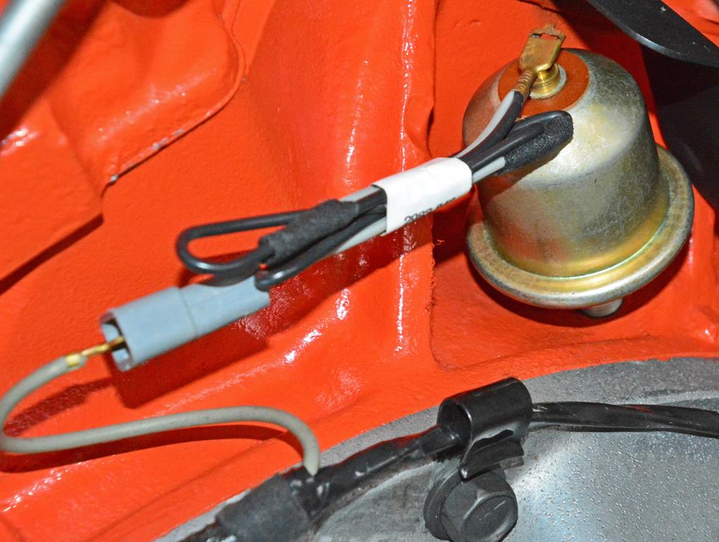
Closer look at the dated oil pressure sending unit with oil pressure resistance wire (typically missing) and the tab routing the Reverse wire.
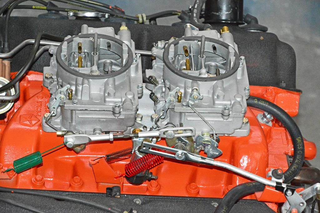
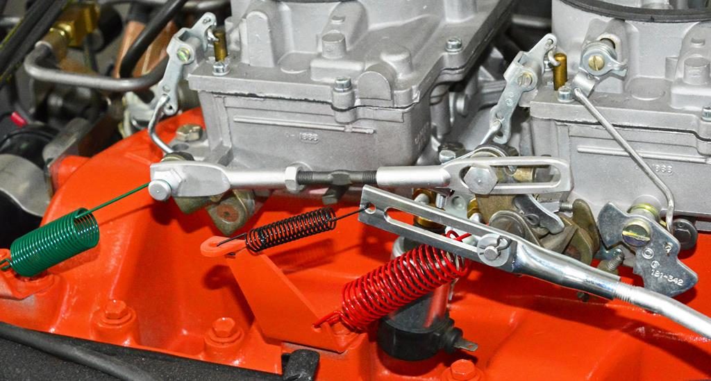
General shots of all the linkage hooked up and kickdown linkage shows the correct hookup and positioning of the spring front and rear carb springs and kickdown spring. Note correct carb gaskets and studs.
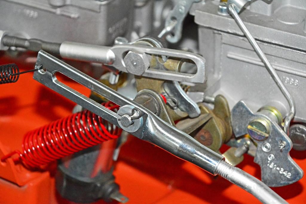
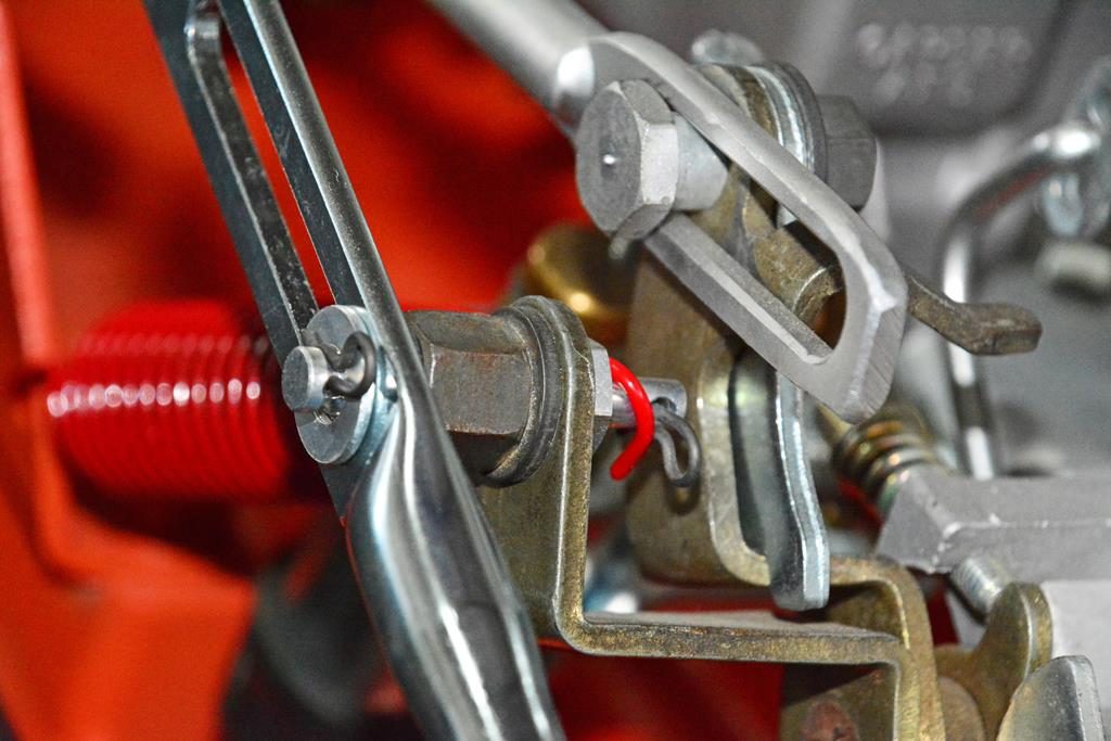
Closer view of the kickdown linkage. Note detail and plating. Bellcrank on Hemi is not painted—it’s not part of the engine assembly and is installed later (a lot of restorers get this wrong.) Kickdown linkage slide, unique to Hemi, incorporates a hole for the auto throttle linkage return spring. Correct Hemi throttle cable is also unique to a Hemi in that incorporates a hole for the retainer clip and the washer. The other side of the linkage is where the throttle cable ferrule will go onto the inner portion of the stud. Note the length and style of the stud. Also seen is the upper solenoid adjusting bracket.
Correct dust cover for the flywheel at the transmission.
Paint on manifold didn’t take time to make it pretty so you see varying degrees of paint on everything. Sometime paint on bottom of oil pan, sometimes you see it. All depends on the guy and how the paint flowed.
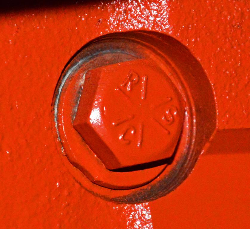
Main cross bolts head design most always RSC Grade 8 bolt with 6 hash marks.
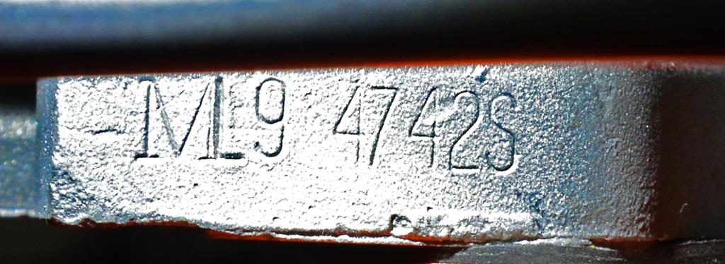
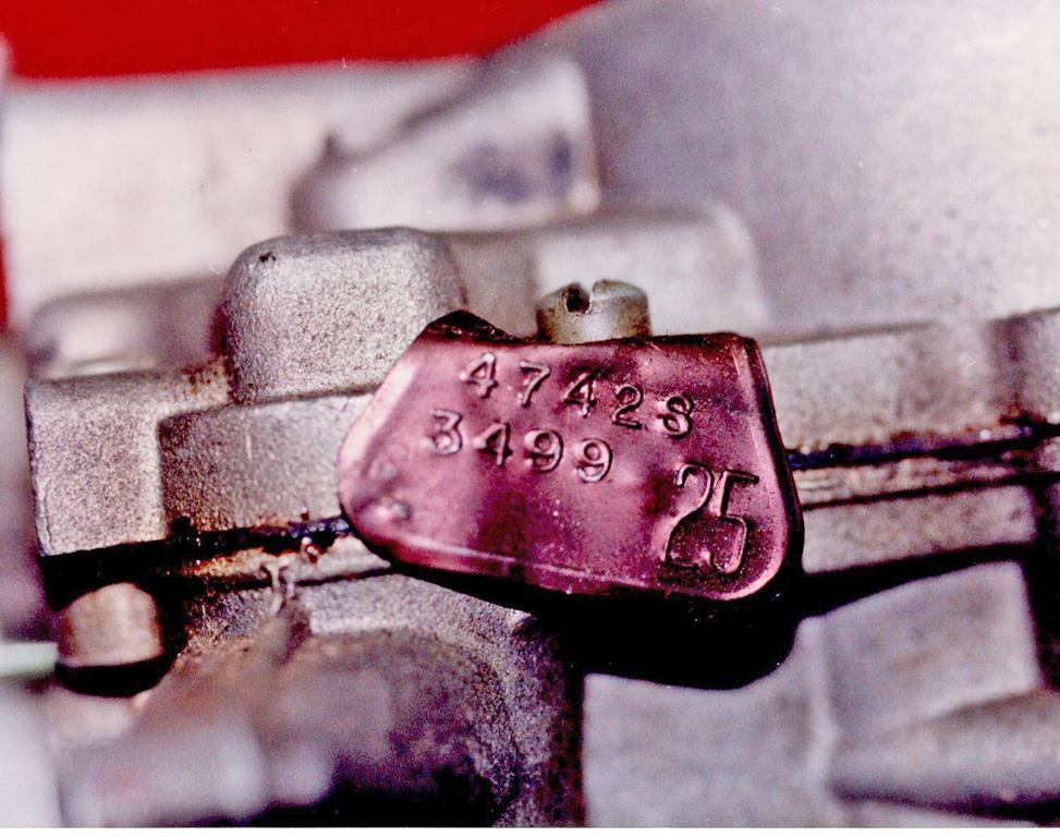
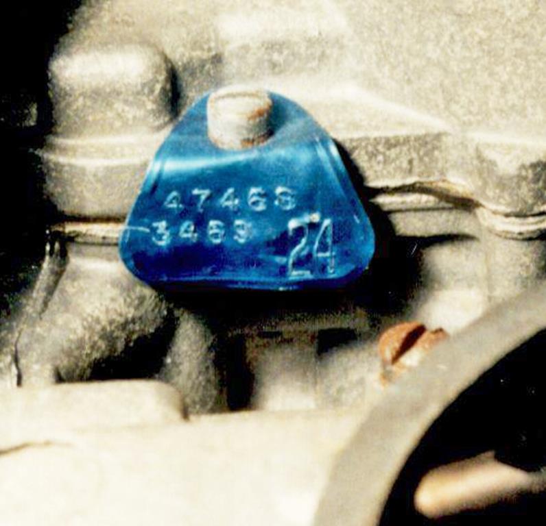
The ML9 on the base of the carb signifies a build date Nov./Dec. ’69. The 4742S is the Carter assigned number. This is only a ‘71 thing–a modified ‘70 carb. You don’t see this for ‘70 Hemi engines. The front carb tag is black (for auto and 4-speed). This is an original black which from age and heat turns to a brownish or copper color like the one here. The top number always corresponds to the carb base number. The lower number is the assembly date. Here, the 3499 is the 349th day of ‘69 which puts the final assembly in December. Tag dates are typically keyed to the carb base date. The rear carb tag (also the original) is blue denoting auto trans. A 4-speed car would have a red tag. The large number in the lower right corner corresponds to the last 2 digits of the carb part number in the Chrysler parts book. Note that these are not the only carbs used for ’71. However, they are found on many. We do have documented original ‘71 Hemis with ‘71 carb numbers. With the advent of repro tags we’re seeing a lot of mistakes regarding the carb base date correlating to final assembly. Many restorers have not thoroughly researched this and are unaware of the proper dating structure and use random numbers. These dates are not random, there are specific dates for tags keyed to the build/assembly of the carb.
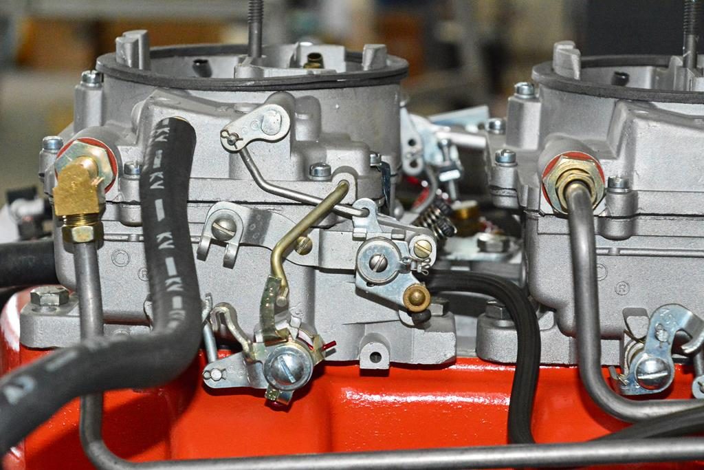
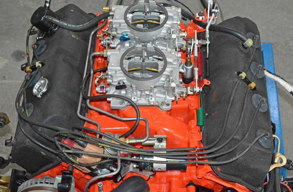
Unique ’71 manual choke assembly. A special bracket mounts to the rear carb holds the manual choke cable. This does away with all the choke tubes on ’70 and earlier Hemis. Note the fuel inlet fittings with correct red Carter gaskets. The front carb fitting is thicker than the special thin rear one.
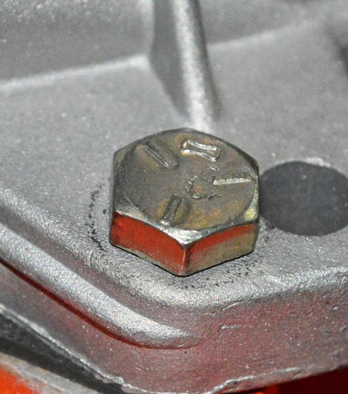
Correct cad-plated Grade 5 carb bolt is unique to the Hemi. The unique head marking is referred to as the “dog bone” design and has 3 hash marks. Grade 5.
The Intake was taped pretty sloppily prior to painting leaving bare spots between and underneath the two carburetors.
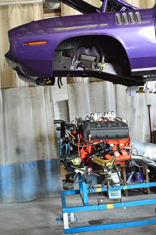
All ready for installation. Badalson use a jig very similar to the factory’s for a no-hassle install. ‘71 ended up being a low production year for the Hemi. By all records available, approx. 356 Hemis were produced. It is not uncommon to find late ‘69 and early ‘70 dated parts used throughout 1971 Hemi production.